PD Controller
The PD (Proportional-Derivative) controller is the core of the integration. It runs event-driven — recalculating each time the grid consumption sensor publishes a new value — and adjusts battery power to keep grid flow close to the configured target (default: 0 W).
Algorithm
error = grid_power - target_power

P = Kp × error
D = Kd × (error - previous_error) / dt

adjustment = P + D
new_power = current_power + adjustment
Because the loop is event-driven (variable cadence), the P term and the rate limit are internally scaled by the real elapsed time between sensor updates, so the tuning behaves the same regardless of how fast your sensor publishes.
Default parameters
| Parameter | Value | Description |
|---|---|---|
Kp |
0.35 |
Proportional gain |
Kd |
0.3 |
Derivative gain |
| Deadband | ±40 W |
Dead zone: ignores small errors |
| Rate limit | ±800 W/cycle |
Maximum change per cycle |
Lowered defaults
Kp/Kd were lowered from 0.65/0.5 to 0.35/0.3 to curb overshoot under the event-driven loop. Installs still on the old defaults are migrated automatically; hand-tuned values are left untouched.
Tuning profiles
Instead of tuning the gains by hand, pick a tuning profile (select.*_pd_tuning_profile) — a one-click preset that sets Kp, Kd and the rate limit together. Profiles are ordered smoothest → fastest:
| Profile | Kp | Kd | Rate limit | Use when |
|---|---|---|---|---|
| Very smooth | 0.22 | 0.15 | 400 W | Noisy meter, want zero hunting; calm but slow |
| Smooth | 0.30 | 0.25 | 600 W | Conservative |
| Balanced | 0.35 | 0.30 | 800 W | Default — works for most installs |
| Aggressive | 0.55 | 0.45 | 1200 W | Clean meter, want a fast response |
| Very aggressive | 0.75 | 0.45 | 2000 W | Clean meter + battery at full power; fastest response |
| Custom | — | — | — | Manual: tune the sliders yourself |
- Selecting a profile writes its three gains and hot-reloads them (no restart).
- Moving any of those three sliders by hand switches the profile to Custom automatically; your value is kept.
- Deadband is not part of the profiles. It is your precision / meter-noise preference and the reference the control-quality sensor measures against, so it stays a separate slider you own. Changing it does not change the active profile.
Limited battery output power
If you cap the battery's output power (system or per-battery max charge/discharge) below a profile's rate limit, the rate limiter never engages — the whole 0→limit range fits in a single cycle, so the controller can jump straight to the cap in one step. The output stays correct and there is no windup (the internal baseline saturates at the cap), but the move is abrupt — more relay wear and possible overshoot before it settles. On a power-limited battery, prefer a smoother profile, or use Custom with a rate limit below your cap. Very aggressive (2000 W) is meant for a battery running at full power.
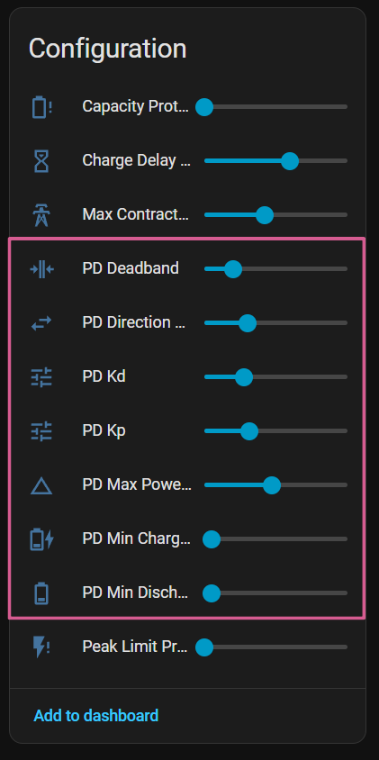
In the dashboard, the profile selector and the quality sensor sit at the top of the PD controller section of the Control tab.
Control quality sensor
sensor.marstek_venus_system_pd_control_quality shows, at a glance, how well the PD is holding the grid target — so you can see the effect of a profile/slider change instead of guessing.
The state is a verdict, not a number:
| State | Meaning | What to do |
|---|---|---|
| Stable | PD tracks the target well | Nothing |
| Oscillating | Hunting (frequent charge↔discharge) | Use a smoother profile, or raise the deadband |
| Sluggish | Too slow to catch up | Use a more aggressive profile |
| Battery limited | Battery full/empty or at its power rail — the PD cannot act | Not a tuning issue |
| Collecting data | Warming up (just started) | Wait |
The attributes carry the raw figures: rms_error_w (average grid-tracking error), oscillation_per_min, the active gains, and active_profile.
How to tune:
- Watch the verdict (and
rms_error_w). Oscillating→ step down a profile (Aggressive → Balanced → Smooth).Sluggish→ step up.- Wait 1–2 minutes — the metric is a 60 s rolling average, so it lags a change.
- Repeat until
Stable.
The metric is robust against false readings: it pauses briefly after any target change (hourly net balance, capacity protection, a manual target change…) and while the battery is limited, so neither inflates the reading.
Control cadence
The controller is event-driven: it recalculates the moment the grid consumption sensor publishes a new value, so it reacts at the sensor's native rate (often once per second) instead of waiting for a fixed timer tick.
A periodic 2-second watchdog runs in parallel. While the sensor is updating normally it does almost nothing — the event has already handled the latest value. Its job is to keep the time-based subsystems running and to force a safety recalculation if the sensor goes silent (after ~30 s without updates the controller re-evaluates instead of holding the last command indefinitely).
Overlapping runs are prevented by a lock: if a cycle is still in progress when the next trigger fires, that trigger is skipped (the running cycle already reads the current state). This keeps the battery Modbus writes serialised.
Stabilisation mechanisms
Deadband (dead zone)
If the error is less than ±40 W, the controller does not adjust power. This prevents continuous micro-oscillations caused by sensor noise.
Rate limiting
Power changes are limited per cycle to smooth transitions and protect the battery from abrupt changes. A "cycle" is one control update, driven by each new sensor value. The configured per-cycle limit is internally scaled by the real elapsed time between updates, so the effective ramp rate (W/s) stays constant regardless of how fast the sensor publishes. Lower the limit if the response feels abrupt.
Oscillation detection
The controller monitors frequent direction reversals (charge↔discharge). If sustained oscillation is detected, the effective gain is temporarily reduced.
Directional hysteresis
Prevents direction changes from momentary load variations (such as appliance start-ups). The controller requires the error to exceed a threshold for several cycles before switching from charging to discharging or vice versa.
Derivative filtering
The derivative term is low-pass filtered (short time constant) before it reaches the output. Differentiating a barely-smoothed grid signal would otherwise amplify meter quantisation and inverter PWM noise and inject it into battery power; filtering keeps the derivative useful without that noise.
Measured-power anti-windup
The controller assumes each battery delivers exactly the power it was commanded. When a battery cannot — for example because of SOC/voltage taper or ramp lag — the controller detects the sustained shortfall by comparing the command against the measured AC power, and re-anchors its internal baseline to reality. This prevents the control output from "winding up" past what the hardware actually delivered, which would otherwise cause an overshoot or a brief grid export when the load later drops.
Relay and write-rate protection
Two optional sliders protect the hardware from chatter when the grid hovers around the deadband edge or a fast meter publishes bursts. Both default to a near-disabled value, so existing installs are unchanged.
| Slider | Default | What it does |
|---|---|---|
PD Relay Cooldown (number.*_pd_relay_cooldown, s) |
0 (off) |
Minimum time the battery stays engaged before returning to idle. Stops relay on/off chatter during solar ramp-up/down. The dwell is timed from the moment idle is requested, so it actually holds. While held it runs at the configured min charge/discharge power (or 100 W if that is 0). Large imbalances bypass it. Only gates active→idle, not charge↔discharge flips. |
PD Min Cycle Interval (number.*_pd_min_cycle_interval, s) |
1 |
Caps how often the event-driven loop runs — grid updates closer together than this are dropped, so a fast meter can't flood slow Modbus bridges (e.g. Elfin EW11) with write bursts. The 2 s safety watchdog is never gated, so control never stalls. 0 = disabled. |
No-PD direct tracking mode
An opt-in alternative to the PD control law, for users who want the battery to follow the consumption sensor 1:1 in a single cycle — no integral, derivative, smoothing, rate limiter or hysteresis. Enable it with the No-PD Direct Tracking switch (switch.*_no_pd_mode); the PD controller is unchanged and untouched while it is off (the two are mutually exclusive in the dashboard).
Each cycle it reconstructs the home load from the battery's measured AC power (new = measured − error) rather than from the last command, so it stays stable across the multi-second inverter ramp instead of oscillating rail-to-rail.
It reuses the existing deadband, min charge/discharge power, relay min-ON and grid-setpoint sliders, plus one mode-specific knob:
- No-PD Command Delay (
number.*_no_pd_command_delay, s) — debounces fast meters by collapsing a burst of updates into a single command on the latest value.
When to use it
No-PD suits a clean, fast meter where you want the most direct possible response and find PD tuning unnecessary. On a noisy meter the PD controller's filtering is usually the better choice.
Backup function exclusion
A battery is excluded from the PD controller when both of the following are true:
- The Backup Function switch (
switch.*_backup_function) is enabled. - The AC Offgrid Power sensor (
sensor.*_ac_offgrid_power) reports a non-zero value — confirming the battery is actually providing offgrid power.
Having the switch on alone is not sufficient. If the switch is on but AC offgrid power reads 0 W (the battery is not actively serving an offgrid load), it continues to participate in PD control normally.
While excluded, the controller sends no power commands, force mode changes, or configuration register writes to the battery. The battery continues to be polled normally so all read-only sensors (SOC, power, temperature, etc.) remain up to date.
Post-backup cooldown
When the offgrid load drops back to 0 W, the battery does not re-enter PD control immediately. A 5-minute cooldown keeps the battery excluded after the backup event ends. This avoids sending write commands to a battery that may still be settling after a backup episode.
Turning the Backup Function switch off clears the cooldown immediately.
Info
This exclusion also covers the weekly full charge register writes and the shutdown sequence.
Per-slot target power
Each time slot can have its own target grid power (target_grid_power), allowing different strategies at different times of day.