Multi-battery management
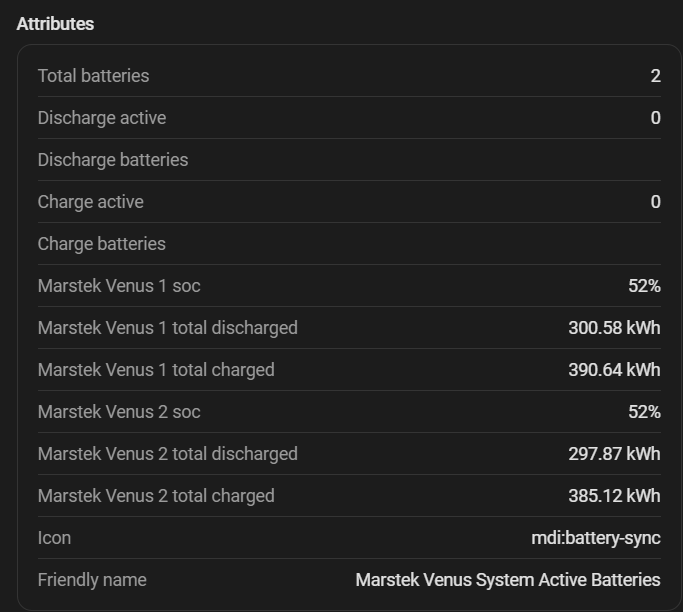
The integration manages up to 6 batteries as an aggregated system, distributing power intelligently to maximise efficiency.
Efficiency principle
Based on measured Venus efficiency curves, batteries are activated only when total power exceeds the efficiency crossover point — the wattage at which splitting load across two batteries becomes more efficient than running one alone. Running fewer batteries at higher power is more efficient than spreading the same load across all of them.
The crossover points (derived from η external measurements) are:
| Direction | Crossover | % of 2500 W physical max |
|---|---|---|
| Discharge | 1500 W | 60 % |
| Charge | 1750 W | 70 % |
The activation threshold is computed dynamically as crossover_W ÷ configured_max_W, clamped to [50 %, 95 %]. This means users who configure a lower power limit per battery activate additional batteries later (closer to their configured max), which correctly reflects that their operating range stays within the single-battery efficiency peak.
The following measurements show DC power consumption/output, AC power at the meter (internal clamp) and at the wall outlet (external clamp), and the resulting efficiency at each power level:
Charging
| % of max | Setpoint (W) | DC internal (W) | AC internal (W) | AC external (W) | η internal | η external |
|---|---|---|---|---|---|---|
| 3 % | 63 | 41 | 58 | 68 | 70.7 % | 60.3 % |
| 5 % | 125 | 105 | 123 | 136 | 85.4 % | 77.2 % |
| 10 % | 250 | 232 | 247 | 262 | 93.9 % | 88.5 % |
| 15 % | 375 | 357 | 372 | 387 | 96.0 % | 92.2 % |
| 20 % | 500 | 481 | 497 | 513 | 96.8 % | 93.8 % |
| 25 % | 625 | 604 | 621 | 639 | 97.3 % | 94.5 % |
| 30 % | 750 | 727 | 743 | 766 | 97.8 % | 94.9 % |
| 35 % | 875 | 850 | 871 | 892 | 97.6 % | 95.3 % |
| 40 % | 1000 | 973 | 995 | 1019 | 97.8 % | 95.5 % |
| 45 % | 1125 | 1095 | 1120 | 1146 | 97.8 % | 95.5 % |
| 50 % | 1250 | 1245 | 1271 | 1274 | 98.0 % | 97.7 % |
| 55 % | 1375 | 1339 | 1369 | 1401 | 97.8 % | 95.6 % |
| 60 % | 1500 | 1460 | 1494 | 1530 | 97.7 % | 95.4 % |
| 65 % | 1625 | 1581 | 1618 | 1658 | 97.7 % | 95.4 % |
| 70 % | 1750 | 1702 | 1743 | 1786 | 97.6 % | 95.3 % |
| 75 % | 1875 | 1823 | 1868 | 1916 | 97.6 % | 95.1 % |
| 80 % | 2000 | 1942 | 1992 | 2044 | 97.5 % | 95.0 % |
| 85 % | 2125 | 2062 | 2117 | 2175 | 97.4 % | 94.8 % |
| 90 % | 2250 | 2183 | 2242 | 2304 | 97.4 % | 94.7 % |
| 95 % | 2375 | 2304 | 2366 | 2436 | 97.4 % | 94.6 % |
| 100 % | 2500 | 2424 | 2491 | 2567 | 97.3 % | 94.4 % |
Discharging
| % of max | Setpoint (W) | DC internal (W) | AC internal (W) | AC external (W) | η internal | η external |
|---|---|---|---|---|---|---|
| 3 % | 63 | 80 | 63 | 60 | 78.8 % | 75.0 % |
| 5 % | 125 | 160 | 124 | 118 | 77.5 % | 73.8 % |
| 10 % | 250 | 284 | 249 | 243 | 87.7 % | 85.6 % |
| 15 % | 375 | 416 | 373 | 368 | 89.7 % | 88.5 % |
| 20 % | 500 | 550 | 498 | 494 | 90.5 % | 89.8 % |
| 25 % | 625 | 685 | 623 | 619 | 90.9 % | 90.4 % |
| 30 % | 750 | 820 | 747 | 745 | 91.1 % | 90.9 % |
| 35 % | 875 | 956 | 872 | 870 | 91.2 % | 91.0 % |
| 40 % | 1000 | 1092 | 997 | 996 | 91.3 % | 91.2 % |
| 45 % | 1125 | 1230 | 1121 | 1121 | 91.1 % | 91.1 % |
| 50 % | 1250 | 1369 | 1246 | 1246 | 91.0 % | 91.0 % |
| 55 % | 1375 | 1507 | 1370 | 1372 | 90.9 % | 91.0 % |
| 60 % | 1500 | 1647 | 1495 | 1497 | 90.8 % | 90.9 % |
| 65 % | 1625 | 1789 | 1620 | 1623 | 90.6 % | 90.7 % |
| 70 % | 1750 | 1931 | 1745 | 1748 | 90.4 % | 90.5 % |
| 75 % | 1875 | 2073 | 1869 | 1874 | 90.2 % | 90.4 % |
| 80 % | 2000 | 2218 | 1994 | 1999 | 89.9 % | 90.1 % |
| 85 % | 2125 | 2362 | 2118 | 2124 | 89.7 % | 89.9 % |
| 90 % | 2250 | 2508 | 2243 | 2250 | 89.4 % | 89.7 % |
| 95 % | 2375 | 2654 | 2368 | 2375 | 89.2 % | 89.5 % |
| 100 % | 2500 | 2801 | 2492 | 2501 | 89.0 % | 89.3 % |
Selection priorities
Discharge
Highest SOC first: the most charged battery discharges first to balance the state of charge across the system.
Charging
Lowest SOC first: the least charged battery receives energy first.
Hysteresis
To avoid "ping-pong" activation/deactivation, three hysteresis levels are applied:
| Hysteresis | Value | Description |
|---|---|---|
| SOC | 5 % | An active battery stays active until another exceeds it by 5% SOC |
| Lifetime energy | 2.5 kWh | Breaks SOC ties using accumulated lifetime energy with an advantage for the active battery |
| Power | 10 pp | Activation threshold derived from efficiency crossover; deactivation = activation − 10 percentage points |
Power distribution
Once active batteries are selected, the total power calculated by the PD controller is distributed among them proportionally, respecting each battery's individual power and SOC limits.
Optional system-wide caps can also be configured in Advanced PD controller after enabling Enable system power limits:
| Setting | Effect |
|---|---|
System Max Charge Power |
Caps the combined charge power across all active batteries |
System Max Discharge Power |
Caps the combined discharge power across all active batteries |
Set either value to 0 W to disable that direction's cap. These limits are applied after per-battery eligibility is determined and before power is distributed, so one battery can still use its full individual limit when it is the only active battery. If several batteries are active, the combined total is throttled to the configured system cap. The corresponding runtime slider entities are only created when the feature is enabled.
Per-battery charge/discharge controls
Each battery exposes two software switches:
| Switch | Effect |
|---|---|
Allow Charge |
When turned off, this battery is excluded from automatic charging. It may still discharge if Allow Discharge is turned on. |
Allow Discharge |
When turned off, this battery is excluded from automatic discharging. It may still charge if Allow Charge is turned on. |
These switches do not write Modbus control registers directly. They only affect the integration's automatic PD controller. If a battery is active in the disabled direction, the integration sends that battery to 0 W and the next control cycle reallocates power to the remaining eligible batteries.
The state is stored per battery as allow_charge and allow_discharge. Missing values default to enabled, so existing installations keep their previous behavior after updating.
Unified blocker registry
Charge and discharge permissions are resolved through a runtime blocker registry. Blockers can be system-wide or scoped to one battery. The controller checks this registry before deadband and stale-sensor early returns, so an active command is stopped as soon as a blocker appears.
Global blockers include solar charge delay, charge/discharge time slots, price-based discharge control, and EV charger no-telemetry pauses. Per-battery blockers include the Allow Charge and Allow Discharge switches, maximum SOC, minimum SOC, and charge hysteresis. Other availability checks such as backup/off-grid exclusion and non-responsive exclusion remain separate from the blocker registry.
The top-level charge_blocked and discharge_blocked attributes report the effective system state: they become true when a global blocker is active or when every known battery is blocked in that direction. Per-battery details remain visible in battery_charge_blockers and battery_discharge_blockers.
The registry is exposed on the Integration Status diagnostic sensor through these attributes:
charge_blockeddischarge_blockedcharge_blockersdischarge_blockersbattery_charge_blockersbattery_discharge_blockers
Non-responsive battery exclusion
When a battery consistently fails to deliver the commanded power — for example due to a Modbus communication glitch or a firmware self-protection response — the integration detects this and temporarily removes it from the active pool.
A battery is flagged as non-responsive when its measured output is below 5% of the commanded setpoint for 3 consecutive control cycles. Once flagged, it enters a 5-minute exclusion window during which it receives no new commands and the remaining batteries absorb its share of the load. After the window expires the fail counter resets and the battery becomes eligible again.
Discharge refusals at low SOC are exempt. At or below 20% SOC (or just above the configured minimum SOC), the BMS can cut discharge on its own — for example a weak cell sagging under load — even though the reported SOC is still above the minimum. The battery then acknowledges the command but delivers 0 W; this is treated as an expected BMS cutoff rather than a fault, so it stays in the pool. This mirrors the high-SOC BMS-cutoff handling on the charge side.
This mechanism prevents a single misbehaving battery from silently degrading system performance without raising alarms or requiring manual intervention.
Compatible modes
Multi-battery distribution applies in all modes: - Normal PD control - Solar charging - Predictive grid charging