Advanced options
After configuring predictive charging, the wizard offers five additional optional steps that adjust the integration's behaviour in specific situations.
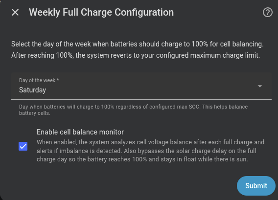
Weekly full charge
Forces a 100% charge once a week for cell balancing. You only need to select the day of the week.
| Field | Description | Default |
|---|---|---|
| Day of the week | On this day the battery will charge to 100% for cell balancing | — |
See Weekly full charge for how it works.
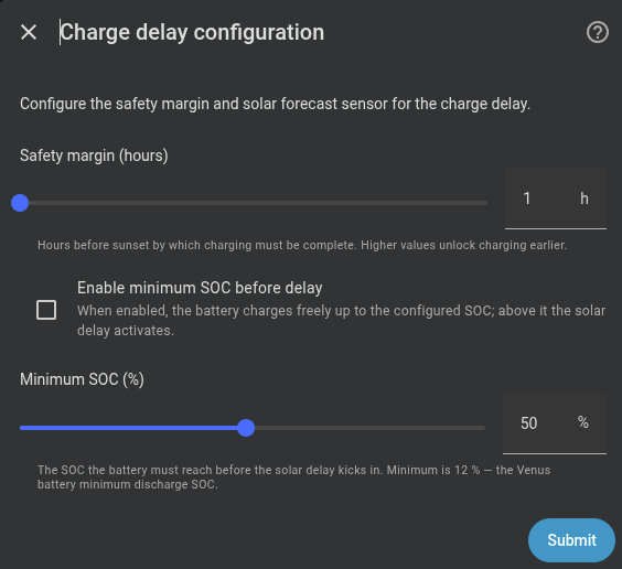
Solar charge delay
Delays morning grid charging while the expected solar production can cover the required energy.
| Field | Description | Default |
|---|---|---|
| Safety margin (h) | Hours before sunset by which charging must be complete | 1 h |
| Solar forecast sensor | Only if not configured in the initial setup step | — |
| Enable minimum SOC before delay | if enabled battery will charge to configured SOC before solar charge delay | Disabled |
| Minimum SOC (%) | Battery SOC to reach before solar charge delay kicks in | — |
A larger margin (e.g. 180 min) unlocks grid charging earlier in the day; a smaller margin waits longer for the sun to cover the energy.
See Solar charge delay for how it works.
Capacity protection (peak shaving)
Limits discharge when SOC drops below a threshold, covering only consumption peaks that exceed a configurable power limit.
| Field | Description | Default | Range |
|---|---|---|---|
| SOC threshold (%) | Protection activates below this % | 30 % |
20-100 % |
| Peak limit (W) | Grid power threshold. The battery discharges the excess above this limit if capacity protection is active | 2500 W |
500-10000 W |
See Peak shaving for how it works.

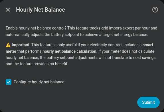
Hourly net balance
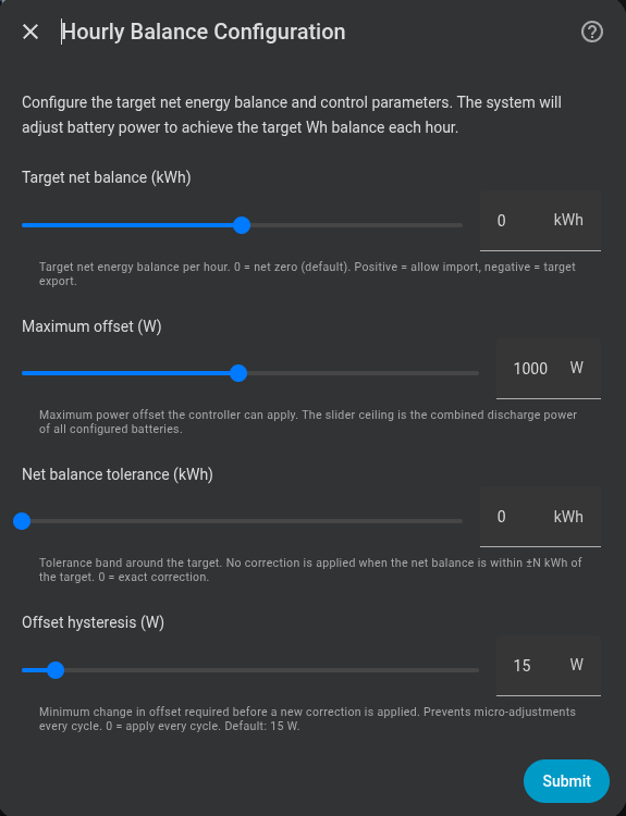
Tracks grid import and export within each civil hour and adjusts the PD setpoint in real time to drive the net energy toward a configurable target. The default target is 0 Wh — net zero each hour — but you can shift it to allow a fixed import or target a fixed export.
| Field | Description | Default |
|---|---|---|
| Target net balance (kWh) | Target net energy balance (0=net zero, positive=net import, negative=net export) | 0 kWh |
| Maximum offset (W) | Maximum power offset the controller can apply (sum of all batteries) | 1000 W |
| Net balance tolerance (kWh) | Tolerance band around target (0=no correction) | 0 kWh |
| Offset hysteresis (W) | Minimum change in offset before corrections are applied (0=apply every cycle) | 15 W |
See Hourly net balance for how it works.
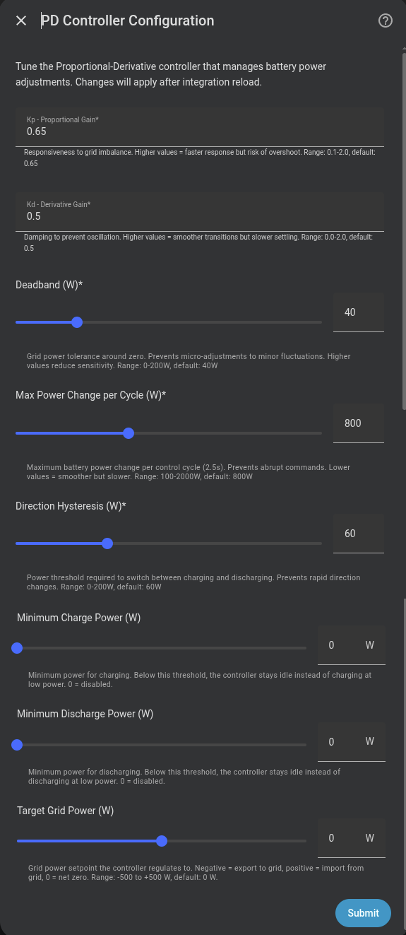
Advanced PD controller
Expert users only
Do not modify these values unless you understand PD control theory and how it interacts with inverter response times. Default values work correctly for the vast majority of installations.
Allows tuning the internal PD controller parameters. All values can also be adjusted at runtime from the integration's configuration entities without restarting.
Prefer profiles
Most users don't need to touch these by hand. The PD tuning profile selector applies vetted Kp/Kd/rate-limit presets in one click, and the PD Control Quality sensor shows whether the result is stable, oscillating or sluggish. See PD controller → Tuning profiles.
| Parameter | Default | Range | Description |
|---|---|---|---|
| Kp | 0.35 |
0.1 – 2.0 | Proportional gain. Higher = faster response but more overshoot |
| Kd | 0.3 |
0.0 – 2.0 | Derivative gain. Higher = smoother transitions but slower response |
| Deadband | 40 W |
0 – 200 W | Dead zone. Controller does not act if the error is smaller than this value |
| Max power change | 800 W/cycle |
100 – 2000 W | Maximum change per cycle. Protects against abrupt swings |
| Direction hysteresis | 60 W |
0 – 200 W | Margin required to switch between charging and discharging |
| Min charge power | 0 W |
0 – 2000 W | If the controller calculates charge below this value, it stays idle. 0 = disabled |
| Min discharge power | 0 W |
0 – 2000 W | Same as above but for discharge. 0 = disabled |
| Enable system power limits | off |
on/off | Enables the system-wide charge/discharge cap feature |
| System max charge power | 0 W |
0 – 15000 W | Optional cap for the combined charge power of all active batteries. 0 = disabled |
| System max discharge power | 0 W |
0 – 15000 W | Optional cap for the combined discharge power of all active batteries. 0 = disabled |
The min charge/discharge power parameters are useful to prevent inefficient micro-cycling when grid demand is very low.
The system max charge/discharge caps are useful when the installation has a shared hardware or wiring limit. They do not reduce each battery's individual maximum: if only one battery is active, it can still use its own configured limit; when several batteries are active, the controller throttles the combined total to the configured system cap.
When Enable system power limits is off, both caps are ignored and their runtime number entities are not created. When enabled, the caps are exposed as slider entities on the Marstek Venus System device.